
Monday, February 1, 2010
Sunday, January 31, 2010
BCMSN - Redundancy: GLBP - Explanation & Configuration [CCNP]
GLBP: Explanation
GLBP can load-balance between the 2 gateways. Instead of having one Active/Standby or one Master/Backup, the GLBP can have multiple active scenarios where both of the routers (L3Switches) are responding to requests.We could do completely equal load-balancing or we could end-up having unequal load-balancing, whatever we choose.
It can load-balance by mapping the VIP to 2 virtual mac-addresses.

(Srv1 is the one on the left )
-When Srv1 sends an ARP for the VIP, that ARP request gets forwarded to the AVG (Primary router) the AVG replies saying the VIP belongs to me.
-When Srv2 sends an ARP for the VIP, again the ARP request goes to the AVG (Primary router not the Backup router) but this time the AVG replies by saying the VIP belongs his buddy BR (Backup router)
This way both links get approximately utilised thanks to the AVG (PR) which acts as the 'Point Man'.
GLBP: Differences from HSRP and VRRP
-Single VIP with multiple macs
-Active Virtual gateway (AVG) acts as the 'Point Man'.
-Other routers act as Active Virtual Forwarders (AVF) eg: BR (backup routers). If there are multiple backup routers & the primary goes down, it elects the BR with the highest priority as the new PR. (Same system as HSRP)
GLBP: Configuration:
Step 1 - Configure GLBP group on the specific physical interface & Set Priority
Step 2 - Optimize Settings (TImers)
Step 3 - Enable load-balancing
L3Switch#conf t
L3Switch(config)#int fa0/0
L3Switch(config-if)#glbp 1 ip 172.30.4.70 (1 being the grp-no followed by the desired VIP)
L3Switch(config-if)#glbp 1 priority 150 (highest priority becomes the Active Virtual Gateway - AVG)
L3Switch(config-if)#glbp 1 timers ? (same as HSRP - Hello & hold timers can be tweaked)
L3Switch(config-if)#glbp 1 load-balancing ? (/enter)
(3 options here:
host-dependent - AVG forwards the same mac-address to clients
round-robin - (default) AVG sends both mac-addresses alternatively
weighted - you can proportionate but you have to setup the algorithm.)
We could leave it at default.
and that is all on GLBP. I believe only GLBP is part of the BCMSN curriculum, HSRP and VRRP arn't.
Further information on redundancy protocols (optional)
(1) Hot Standby Router Protocol (HSRP) - RFC 2281
(2) Virtual Router Redundancy Protocol (VRRP) - RFC 2338
(3) Gateway Load Balancing protocol (GLBP)
(4) Server Load Balancing (SLB)
This is another redundancy protocol where you can take a group of servers (server farm) and configure the router to display them as one entity.
and that completes the switching curriculum of BCMSN. Not bad for one month seeing we've completed the switching syllabus of the exam. Beginning the new month will be a new topic - Wireless.
BCMSN - Redundancy: VRRP - Explanation & Configuration [CCNP]
VRRP is very similar to HSRP escept it's an open standard and a bit newer.
VRRP & HSRP: Differences
-Active/Standby becomes Master/Backup.
-Standby group becomes VRRP group
-Master router can share Virtual IP . The feature only changes the ip-addr of the Master router (assigns VIP to PR only) whereas the ip for the backup routers (sandby routers) stay the same, the feature is optional and can be used only if you want it that way)
-1 second hello timer (3xhello timer + skew = Down timer.)
-Following is the formula to calculate skew - 256 - 100 (priority) = Ans/256 = 0.x msec is the skew that gets added.
VRRP Configuration:
Step 1 - Configure VRRP Group on the specific physical interface
Step 2 - Optimize settings
Step 3 - Verify
L3Switch#conf t
L3Switch(config)#int fa0/0
L3Switch(config-if)#vrrp 1 ip 172.30.4.90 (1 is the group-no followed by the VIP)
L3Switch(config-if)#vrrp 1 preempt
L3Switch(config-if)#vrrp 1 timers ? (? reveals with 2 options: advertise and learn.)
L3Switch(config-if)#vrrp 1 timers advertise msec 100
L3Switch(config-if)#^z
-In vrrp we don't have to set the dead timer, only just set the hello timer as mentioned earlier. The hold timer is calculated automatically (3xhell time + skew).
-Secondly, the good thing here is that we only have to set the hello timer on the master router (MR), all the other routers are set by default to 'learn' so they'll basically learn their timer based on what the master is using. This is a bonus here compared to HSRP where we have to go on all routers and make sre the timers are set the same on all routers)
Show command for VRRP:
L3Switch#show vrrp
Friday, January 29, 2010
BCMSN - Redundancy: HSRP - Explanation & Configuration [CCNP]
Function of spanning-tree: Provide redundancy between Switch A & B through redundant links.
Function of Etherchannel: Make use of those redundant links by bundling them into 1 high-bandwidth link.
Function of redundancy protocols - HSRP, VRRP, GLBP: These are the three protocols that make redundancy happen.
When a path to a router or a switch fails and there a multiple paths (redundant connections) to get to a VLAN, HSRP, VRRP or GLBP can be used. These protocols make the fail-over to the other link. (GLBP additionally can also load-balance).
HSRP: Explanation
-Created by Cisco for Cisco in 1994
-Uses a default hello timer of 3 seconds with a hold timer of 10 seconds.
-HSRP was the 1st of the three protocols and was originally designed for routers back in 94 as L3 switching wasn't rly there back then.
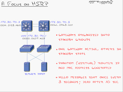
-The ip address 172.30.70.2 and 172.30.70.3 are ip's assigned to the 'interface vlan 70'.
-When I do that, I generate a standby 'virtual ip address' and a'virtual mac address' (VIP - 172.30.70.1 and VMAC - 0000.0c07.ACO1, in this case) that both switches respond to.
-Because HSRP does not load balance like GLBP, only one of the primary routers here will be responding to the virtual ip and mac addresses actively. The other layer 3 switch/es will be on standby and will only become active once the primary goes down.
-The best part is the easy configuration on the clients (server farm in this case) All you have to do there is set the default gateway to 172.30.70.1
-By default, Hello messages are sent every 3 seconds and dead timer is set to 10 seconds. (Not very quick as HSRP was designed for networks in 1994 but the timers are now tunable to VRRP si it can converge just as fast). The only weakness of HSRP is that it's Cisco proprietary.
-The virtual mac-address has a specific structure to it. When you create a standby group, it generates a virtual mac-address with the VIP you specified. This 1st section of this virtual mac-address 0000.0c is the 'Cisco vendor id'. By seeing 07.AC as the 2nd group of digits there, you're going to immediately know that this is HSRP. The last group of digits there - XX (01, in our case) will be the HSRP standby group number. For instance, group 05 would be 05, group 10 would be 0A (in hex).
HSRP: Configuration
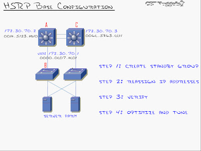
Configuring Switch A as the primary and Switch C as the standby:
Step 1: Create Standby Group for the specific VLAN interface & Set Priority.
SA#conf t
SA(config)#int vlan 70
SA(config-vlan)#standby 1 ip 172.30.70.1 (The command 'standby' tells the router you are after HSRP. '1' represents the standby group number that could be anything between 0 to 255. 'ip' followed by the virtual ip-address or the phantom ip-address)
SA(config-vlan)#standby 1 priority 150 (By default each router or L3 switch has a default priority of 100. When it comes to priority, the higher the better. If both priorities are same then it chooses the one with the higher ip-address. Thus in this case since we want SA to be the primary L3 switch, we change it's priority to >100)
At this point we have HSRP configured on Switch A. Now to configure SC.
SC#conf t
SC(config)#int vlan 70
SC(config-vlan)#standby 1 ip 172.30.70.1
(We'll leave the default priority of 100 as we want SA to be the primary L3 switch)
Now if we telnet to 172.30.70.1 we'll log-in to the layer 3 switch - SA.
Step 2: Reassign ip address (default-gateway on clients)
At this point we set the default-gateway to '172.30.70.1' on all clients (server farm, in this case)
That's all there is to the base HSRP configuration - 2 commands.
HSRP: Tuning and Optimizing HSRP
(1) Priority (Done)
(2) Pre empt
(3) Tracking
(4) Timers
(2) Pre-empt: Explanation
Once the failover takes place from the active router (L3switch) to the standby router (L3 switch) when the active router goes down, the standby router remains the active router until the standby router goes down.....
...unless you configure pre-emption (preempt)
Preempt brings SA immediately back as active router once the link is back up, it does not wait for SB to go down.
(2) Pre-empt: Configuration (1 cmd)
SA(config)#int vlan 70
SA(config-vlan)#standby 1 preempt
(3) Tracking: Explanation
Interface tracking says that if an interface (e.g suppose s0/0 on SA is connecting to a router) goes down, it will take away a certain amount from its priority
e.g take away 60 from the priority if fa0/1 goes down, in which case it means 150-60 = 90 so SC will now become the active router/L3 switch because it now has a higher priority of 100)
For this feature to work, preempt needs to be enabled of-course.
(3) Tracking: Configuration
SA(config)#int vlan 70
SA(config-vlan)#standby 1 preempt
SA(config-vlan)#standby 1 track serial 0/0 60 (if s0/0 goes down then decrement by 60)
(4) Timers: Explanation
Timers can be tweaked for HSRP to recover quickly on a failover.
SA(config)#int vlan 70
SA(config-vlan)#standby 1 timers 1 4 (hello timer = 1 sec, dead timer = 4 secs)
We can also beat vrrp timers and put milliseconds for hello and hold timers:
SA(config)#int vlan 70
SA(config-vlan)#standby 1 timers msec 150 msec 700 (A less than a second delay is great as it usually means the delay and downtime is unnoticeable. The drawback to this is that the network bandwidth goes up and more importantly the processor cycle goes up)
Lastly...
Show Command for HSRP:
SA#show standby
BCMSN Lab - Multi-Layer Switching (MLS) Configuration [CCNP]

3 steps for the setup
(1) Create SVI's & enable ip routing
(2) Create routed ports (optional)
(3) Enable routing ports (optional)
Step 1 - Create SVI's [Switch Virtual Interface - SVI's take place of a 'router on a stick' (not a physical port)]
S4#conf t
S4(config)#interface vlan 10 (Just like that we have created an SVI 10)
S4(config-if)#ip address 10.1.10.1 255.255.255.0
S4(config-if)#no shut
S4(config-if)#exit
S4(config)#int vlan 20
S4(config-if)#ip addr 10.1.20.1 255.255.255.0
S4(config-if)#no shut
S4(config-if)#exit (this creates SVI's 10 and 20)
S4(config)#ip routing (<-Very imp cmd: This enables you to route between Vlan 10 & Vlan 20)
Step 2 - Create routed ports [In this case, we'll make fa0/3 and fa0/4 routed ports (instead of trunk ports). This makes the L3 switch like another router as if both routers are connected using a crossover cable]
S4(config)#int fa0/3
S4(config-if)#no switchport (This makes it a router)
S4(config-if)#ip address 10.1.3.1 255.255.255.252
S4(config-if)#no shut
S4(config)#int fa0/4
S4(config-if)#no switchport
S4(config-if)#ip address 10.1.4.1 255.255.255.252
S4(config-if)#no shut
S4(config-if)#exit
Step 3 - Enable routing ports
S4(config)#router eigrp 1
S4(config-router)#no auto-summary
S4(config-router)#network 10.0.0.0 (<- This will form a neighbor relationship with the neighboring router...on a switch. (S4, once S4 is configured similarly using the 3 steps)
Lastly, configure S4 similarly, except with different ip's on the same subnet (for ports fa0/3 and fa0/4 that server as it's trunk links)
Note: int fa0/2 on the L3 Switch will remain a 'switchport' (don't use the 'no switchport' cmd there) as that's a trunk port.
Thursday, January 28, 2010
BCMSN - Understanding CEF Optimization [CCNP]
How Cisco switches use CEF (Cisco Express Forwarding)

CEF is the predominately used method for layer 3 switches nowadays. CEF contains a forwarding information base (FIB) for processing L3 information, and an adjacency table that is used for L2 information. Both of them sit in a high-speed cache that is located in the ASIC hardware of the switch (NOT the IOS Software, the slow layer 3/routing layer)
The FIB contains the entire routing table of the network and the adjacency table contains the entire mac-address-table of the network, thus when a packet enters the layer 3 switch, it first goes to the FIB, the FIB then strips open the packet, matches the destination ip with the ip it has in it's routing table matching it with the mac-address from the adjacency table and because it holds all that info it can manage to directly transfer the packet at wire speed.
This is the key concept and one of the big differences between a switch and a switch using CEF that is able to do all this forwarding between VLAN's to routed ports to other routers, all moving at wire speed. It's one of the main advantages of buying a layer 3 switch.
Exceptions to CEF (Packets that don't qualify):
-Packet with header options
-Packet with TTL expired
-Packets destined to a tunnel interface
-Packets with unsupported encapsulations
-Packets requiring fragmentation (MTU exceeded)
Configuring CEF:
Most layer 3 switches that shift from Cisco support CEF by default (as in you have to turn it off if you don't want to use it because it is 'on' by default).
S2#conf t
S2(config)#ip cef (Turns on CEF on the switch)
CEF: Show commands
To verify if CEF is running:
S2#show ip cef
CEF also lets you monitor traffic/statistics -> Use the ? feature: S2(config)#ip cef ?
example (1) S2#show ip cef vlan 20 (Will show all the cached info in the CEF table)
example (2) S2#show ip cef 172.30.2.0 (to see if CEF has learnt about a particular entry, in this
case 172.30.2.0)
'show ip cef summary' is another handy command to use.
BCMSN - L3 Switching (Inter-VLAN Routing) [CCNP]
Inter-VLAN Routing: 2 solutions
(1) Router on a stick
(2)Multi-layer Switching using a Layer 3 switch.
(1) Router on a stick
Drawbacks:
-Single point of faiure
-Congestion on link
-Delay of routing (Routers being slower than switches)
(2) Multi-Layer Switching using a Layer 3 Switch
Advantages:
-Routing at wire speed (switching speed)
-Backplane bandwidth (no unnecessary bandwidth usage between switch and router like with 'router on a stick'.
-Redundancy enabled
Disadvantages:
-Cost (Layer 3 switches can start from $5000 as opposed to $300 - $400 for a normal switch.)
Understanding Layer 3 vs. Multilayer Switching:
When the very first packet goes from one VLAN to another VLAN through the layer 3 switch, that first packet is going to go to the router that is inside of the switch (which though from the outside is a switch, is still a router from the inside hence slow transmission, software-based & so on..) but the key here is that once the first packet has hit the router, the router passes it to the switch-side called CEF (the hardware side of the switch) so all future packets fly through there without having to be checked by the router, thus establishing wire speed.
This is what is known as Multilayer switching.
So what is the difference between a Layer 3 switch and a Multilayer switch?
-A layer 3 switch is a switch with a router inside.
-A multilayer switch is a switch that has the ability to cache route information (CEF)
FACT: Every layer 3 switch is also a multilayer switch but not every multilayer switch is a layer 3 switch.
I'll cover more on CEF in a later post...
Subscribe to:
Posts (Atom)