
Monday, February 1, 2010
Sunday, January 31, 2010
BCMSN - Redundancy: GLBP - Explanation & Configuration [CCNP]
GLBP: Explanation
GLBP can load-balance between the 2 gateways. Instead of having one Active/Standby or one Master/Backup, the GLBP can have multiple active scenarios where both of the routers (L3Switches) are responding to requests.We could do completely equal load-balancing or we could end-up having unequal load-balancing, whatever we choose.
It can load-balance by mapping the VIP to 2 virtual mac-addresses.

(Srv1 is the one on the left )
-When Srv1 sends an ARP for the VIP, that ARP request gets forwarded to the AVG (Primary router) the AVG replies saying the VIP belongs to me.
-When Srv2 sends an ARP for the VIP, again the ARP request goes to the AVG (Primary router not the Backup router) but this time the AVG replies by saying the VIP belongs his buddy BR (Backup router)
This way both links get approximately utilised thanks to the AVG (PR) which acts as the 'Point Man'.
GLBP: Differences from HSRP and VRRP
-Single VIP with multiple macs
-Active Virtual gateway (AVG) acts as the 'Point Man'.
-Other routers act as Active Virtual Forwarders (AVF) eg: BR (backup routers). If there are multiple backup routers & the primary goes down, it elects the BR with the highest priority as the new PR. (Same system as HSRP)
GLBP: Configuration:
Step 1 - Configure GLBP group on the specific physical interface & Set Priority
Step 2 - Optimize Settings (TImers)
Step 3 - Enable load-balancing
L3Switch#conf t
L3Switch(config)#int fa0/0
L3Switch(config-if)#glbp 1 ip 172.30.4.70 (1 being the grp-no followed by the desired VIP)
L3Switch(config-if)#glbp 1 priority 150 (highest priority becomes the Active Virtual Gateway - AVG)
L3Switch(config-if)#glbp 1 timers ? (same as HSRP - Hello & hold timers can be tweaked)
L3Switch(config-if)#glbp 1 load-balancing ? (/enter)
(3 options here:
host-dependent - AVG forwards the same mac-address to clients
round-robin - (default) AVG sends both mac-addresses alternatively
weighted - you can proportionate but you have to setup the algorithm.)
We could leave it at default.
and that is all on GLBP. I believe only GLBP is part of the BCMSN curriculum, HSRP and VRRP arn't.
Further information on redundancy protocols (optional)
(1) Hot Standby Router Protocol (HSRP) - RFC 2281
(2) Virtual Router Redundancy Protocol (VRRP) - RFC 2338
(3) Gateway Load Balancing protocol (GLBP)
(4) Server Load Balancing (SLB)
This is another redundancy protocol where you can take a group of servers (server farm) and configure the router to display them as one entity.
and that completes the switching curriculum of BCMSN. Not bad for one month seeing we've completed the switching syllabus of the exam. Beginning the new month will be a new topic - Wireless.
BCMSN - Redundancy: VRRP - Explanation & Configuration [CCNP]
VRRP is very similar to HSRP escept it's an open standard and a bit newer.
VRRP & HSRP: Differences
-Active/Standby becomes Master/Backup.
-Standby group becomes VRRP group
-Master router can share Virtual IP . The feature only changes the ip-addr of the Master router (assigns VIP to PR only) whereas the ip for the backup routers (sandby routers) stay the same, the feature is optional and can be used only if you want it that way)
-1 second hello timer (3xhello timer + skew = Down timer.)
-Following is the formula to calculate skew - 256 - 100 (priority) = Ans/256 = 0.x msec is the skew that gets added.
VRRP Configuration:
Step 1 - Configure VRRP Group on the specific physical interface
Step 2 - Optimize settings
Step 3 - Verify
L3Switch#conf t
L3Switch(config)#int fa0/0
L3Switch(config-if)#vrrp 1 ip 172.30.4.90 (1 is the group-no followed by the VIP)
L3Switch(config-if)#vrrp 1 preempt
L3Switch(config-if)#vrrp 1 timers ? (? reveals with 2 options: advertise and learn.)
L3Switch(config-if)#vrrp 1 timers advertise msec 100
L3Switch(config-if)#^z
-In vrrp we don't have to set the dead timer, only just set the hello timer as mentioned earlier. The hold timer is calculated automatically (3xhell time + skew).
-Secondly, the good thing here is that we only have to set the hello timer on the master router (MR), all the other routers are set by default to 'learn' so they'll basically learn their timer based on what the master is using. This is a bonus here compared to HSRP where we have to go on all routers and make sre the timers are set the same on all routers)
Show command for VRRP:
L3Switch#show vrrp
Friday, January 29, 2010
BCMSN - Redundancy: HSRP - Explanation & Configuration [CCNP]
Function of spanning-tree: Provide redundancy between Switch A & B through redundant links.
Function of Etherchannel: Make use of those redundant links by bundling them into 1 high-bandwidth link.
Function of redundancy protocols - HSRP, VRRP, GLBP: These are the three protocols that make redundancy happen.
When a path to a router or a switch fails and there a multiple paths (redundant connections) to get to a VLAN, HSRP, VRRP or GLBP can be used. These protocols make the fail-over to the other link. (GLBP additionally can also load-balance).
HSRP: Explanation
-Created by Cisco for Cisco in 1994
-Uses a default hello timer of 3 seconds with a hold timer of 10 seconds.
-HSRP was the 1st of the three protocols and was originally designed for routers back in 94 as L3 switching wasn't rly there back then.
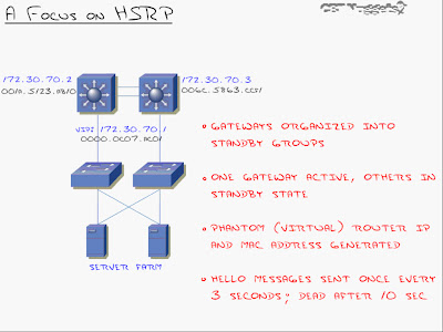
-The ip address 172.30.70.2 and 172.30.70.3 are ip's assigned to the 'interface vlan 70'.
-When I do that, I generate a standby 'virtual ip address' and a'virtual mac address' (VIP - 172.30.70.1 and VMAC - 0000.0c07.ACO1, in this case) that both switches respond to.
-Because HSRP does not load balance like GLBP, only one of the primary routers here will be responding to the virtual ip and mac addresses actively. The other layer 3 switch/es will be on standby and will only become active once the primary goes down.
-The best part is the easy configuration on the clients (server farm in this case) All you have to do there is set the default gateway to 172.30.70.1
-By default, Hello messages are sent every 3 seconds and dead timer is set to 10 seconds. (Not very quick as HSRP was designed for networks in 1994 but the timers are now tunable to VRRP si it can converge just as fast). The only weakness of HSRP is that it's Cisco proprietary.
-The virtual mac-address has a specific structure to it. When you create a standby group, it generates a virtual mac-address with the VIP you specified. This 1st section of this virtual mac-address 0000.0c is the 'Cisco vendor id'. By seeing 07.AC as the 2nd group of digits there, you're going to immediately know that this is HSRP. The last group of digits there - XX (01, in our case) will be the HSRP standby group number. For instance, group 05 would be 05, group 10 would be 0A (in hex).
HSRP: Configuration
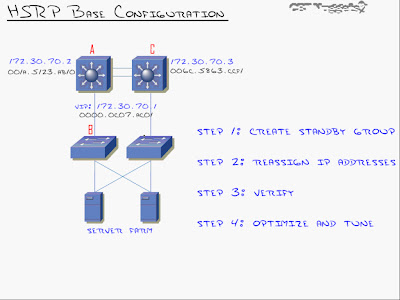
Configuring Switch A as the primary and Switch C as the standby:
Step 1: Create Standby Group for the specific VLAN interface & Set Priority.
SA#conf t
SA(config)#int vlan 70
SA(config-vlan)#standby 1 ip 172.30.70.1 (The command 'standby' tells the router you are after HSRP. '1' represents the standby group number that could be anything between 0 to 255. 'ip' followed by the virtual ip-address or the phantom ip-address)
SA(config-vlan)#standby 1 priority 150 (By default each router or L3 switch has a default priority of 100. When it comes to priority, the higher the better. If both priorities are same then it chooses the one with the higher ip-address. Thus in this case since we want SA to be the primary L3 switch, we change it's priority to >100)
At this point we have HSRP configured on Switch A. Now to configure SC.
SC#conf t
SC(config)#int vlan 70
SC(config-vlan)#standby 1 ip 172.30.70.1
(We'll leave the default priority of 100 as we want SA to be the primary L3 switch)
Now if we telnet to 172.30.70.1 we'll log-in to the layer 3 switch - SA.
Step 2: Reassign ip address (default-gateway on clients)
At this point we set the default-gateway to '172.30.70.1' on all clients (server farm, in this case)
That's all there is to the base HSRP configuration - 2 commands.
HSRP: Tuning and Optimizing HSRP
(1) Priority (Done)
(2) Pre empt
(3) Tracking
(4) Timers
(2) Pre-empt: Explanation
Once the failover takes place from the active router (L3switch) to the standby router (L3 switch) when the active router goes down, the standby router remains the active router until the standby router goes down.....
...unless you configure pre-emption (preempt)
Preempt brings SA immediately back as active router once the link is back up, it does not wait for SB to go down.
(2) Pre-empt: Configuration (1 cmd)
SA(config)#int vlan 70
SA(config-vlan)#standby 1 preempt
(3) Tracking: Explanation
Interface tracking says that if an interface (e.g suppose s0/0 on SA is connecting to a router) goes down, it will take away a certain amount from its priority
e.g take away 60 from the priority if fa0/1 goes down, in which case it means 150-60 = 90 so SC will now become the active router/L3 switch because it now has a higher priority of 100)
For this feature to work, preempt needs to be enabled of-course.
(3) Tracking: Configuration
SA(config)#int vlan 70
SA(config-vlan)#standby 1 preempt
SA(config-vlan)#standby 1 track serial 0/0 60 (if s0/0 goes down then decrement by 60)
(4) Timers: Explanation
Timers can be tweaked for HSRP to recover quickly on a failover.
SA(config)#int vlan 70
SA(config-vlan)#standby 1 timers 1 4 (hello timer = 1 sec, dead timer = 4 secs)
We can also beat vrrp timers and put milliseconds for hello and hold timers:
SA(config)#int vlan 70
SA(config-vlan)#standby 1 timers msec 150 msec 700 (A less than a second delay is great as it usually means the delay and downtime is unnoticeable. The drawback to this is that the network bandwidth goes up and more importantly the processor cycle goes up)
Lastly...
Show Command for HSRP:
SA#show standby
BCMSN Lab - Multi-Layer Switching (MLS) Configuration [CCNP]

3 steps for the setup
(1) Create SVI's & enable ip routing
(2) Create routed ports (optional)
(3) Enable routing ports (optional)
Step 1 - Create SVI's [Switch Virtual Interface - SVI's take place of a 'router on a stick' (not a physical port)]
S4#conf t
S4(config)#interface vlan 10 (Just like that we have created an SVI 10)
S4(config-if)#ip address 10.1.10.1 255.255.255.0
S4(config-if)#no shut
S4(config-if)#exit
S4(config)#int vlan 20
S4(config-if)#ip addr 10.1.20.1 255.255.255.0
S4(config-if)#no shut
S4(config-if)#exit (this creates SVI's 10 and 20)
S4(config)#ip routing (<-Very imp cmd: This enables you to route between Vlan 10 & Vlan 20)
Step 2 - Create routed ports [In this case, we'll make fa0/3 and fa0/4 routed ports (instead of trunk ports). This makes the L3 switch like another router as if both routers are connected using a crossover cable]
S4(config)#int fa0/3
S4(config-if)#no switchport (This makes it a router)
S4(config-if)#ip address 10.1.3.1 255.255.255.252
S4(config-if)#no shut
S4(config)#int fa0/4
S4(config-if)#no switchport
S4(config-if)#ip address 10.1.4.1 255.255.255.252
S4(config-if)#no shut
S4(config-if)#exit
Step 3 - Enable routing ports
S4(config)#router eigrp 1
S4(config-router)#no auto-summary
S4(config-router)#network 10.0.0.0 (<- This will form a neighbor relationship with the neighboring router...on a switch. (S4, once S4 is configured similarly using the 3 steps)
Lastly, configure S4 similarly, except with different ip's on the same subnet (for ports fa0/3 and fa0/4 that server as it's trunk links)
Note: int fa0/2 on the L3 Switch will remain a 'switchport' (don't use the 'no switchport' cmd there) as that's a trunk port.
Thursday, January 28, 2010
BCMSN - Understanding CEF Optimization [CCNP]
How Cisco switches use CEF (Cisco Express Forwarding)

CEF is the predominately used method for layer 3 switches nowadays. CEF contains a forwarding information base (FIB) for processing L3 information, and an adjacency table that is used for L2 information. Both of them sit in a high-speed cache that is located in the ASIC hardware of the switch (NOT the IOS Software, the slow layer 3/routing layer)
The FIB contains the entire routing table of the network and the adjacency table contains the entire mac-address-table of the network, thus when a packet enters the layer 3 switch, it first goes to the FIB, the FIB then strips open the packet, matches the destination ip with the ip it has in it's routing table matching it with the mac-address from the adjacency table and because it holds all that info it can manage to directly transfer the packet at wire speed.
This is the key concept and one of the big differences between a switch and a switch using CEF that is able to do all this forwarding between VLAN's to routed ports to other routers, all moving at wire speed. It's one of the main advantages of buying a layer 3 switch.
Exceptions to CEF (Packets that don't qualify):
-Packet with header options
-Packet with TTL expired
-Packets destined to a tunnel interface
-Packets with unsupported encapsulations
-Packets requiring fragmentation (MTU exceeded)
Configuring CEF:
Most layer 3 switches that shift from Cisco support CEF by default (as in you have to turn it off if you don't want to use it because it is 'on' by default).
S2#conf t
S2(config)#ip cef (Turns on CEF on the switch)
CEF: Show commands
To verify if CEF is running:
S2#show ip cef
CEF also lets you monitor traffic/statistics -> Use the ? feature: S2(config)#ip cef ?
example (1) S2#show ip cef vlan 20 (Will show all the cached info in the CEF table)
example (2) S2#show ip cef 172.30.2.0 (to see if CEF has learnt about a particular entry, in this
case 172.30.2.0)
'show ip cef summary' is another handy command to use.
BCMSN - L3 Switching (Inter-VLAN Routing) [CCNP]
Inter-VLAN Routing: 2 solutions
(1) Router on a stick
(2)Multi-layer Switching using a Layer 3 switch.
(1) Router on a stick
Drawbacks:
-Single point of faiure
-Congestion on link
-Delay of routing (Routers being slower than switches)
(2) Multi-Layer Switching using a Layer 3 Switch
Advantages:
-Routing at wire speed (switching speed)
-Backplane bandwidth (no unnecessary bandwidth usage between switch and router like with 'router on a stick'.
-Redundancy enabled
Disadvantages:
-Cost (Layer 3 switches can start from $5000 as opposed to $300 - $400 for a normal switch.)
Understanding Layer 3 vs. Multilayer Switching:
When the very first packet goes from one VLAN to another VLAN through the layer 3 switch, that first packet is going to go to the router that is inside of the switch (which though from the outside is a switch, is still a router from the inside hence slow transmission, software-based & so on..) but the key here is that once the first packet has hit the router, the router passes it to the switch-side called CEF (the hardware side of the switch) so all future packets fly through there without having to be checked by the router, thus establishing wire speed.
This is what is known as Multilayer switching.
So what is the difference between a Layer 3 switch and a Multilayer switch?
-A layer 3 switch is a switch with a router inside.
-A multilayer switch is a switch that has the ability to cache route information (CEF)
FACT: Every layer 3 switch is also a multilayer switch but not every multilayer switch is a layer 3 switch.
I'll cover more on CEF in a later post...
BCMSN - Switch Port Analyzer (SPAN) [CCNP]
SPAN: Description [Credits to ETts for this explanation]
Suppose, for instance, that you want to examine traffic flowing in and out of a port, or within a virtual local-area network (VLAN). In a shared network, such as Ethernet, you would attach a network analyzer to an available port on the hub and your analyzer would listen to all traffic on the segment, as illustrated in the figure.

The analyzer decodes the frames and provides you with an analysis of the frame contents, such as the packets and other higher-layer protocol information.
In a switched network, however, this is not as simple as in a shared network. In a switched network, the switch filters frames from transmitting out a port unless the bridge/switch table believes the frame's destination is on that port, or the frame needs to be flooded, such as during a spanning-tree update. This is not going to work for you because you want to see all the switch traffic, from all the VLANs. The SPAN switch feature enables you to attach an analyzer on a switch port and capture traffic from other ports in the switch, as illustrated in the figure below.

The SPAN port mirrors traffic from one or more source interfaces on any VLAN, or from one or more VLANs to a destination port for analysis. The network analyzer attaches to the SPAN port and examines the traffic as it passes through the switch. The network analyzer enables you to dig into the details of your network traffic. For SPAN configuration, the source interfaces and the destination interface must be on the same switch.
NOTE: SPAN does not affect the switching of network traffic on source interfaces; copies of the frames received or transmitted by the source interfaces are sent to the destination interface.
http://www.cisco.com/en/US/products/hw/switches/ps708/products_tech_note09186a008015c612.shtml
SPAN: Configuration
Scenario: In order to configure port Fa0/1 as a destination port, the source ports Fa0/2 and Fa0/5, and the management interface (VLAN 1), select the interface Fa0/1 in the configuration mode.
Step 1: Enter destination port
S4#conf t
S4(config)#int fa0/1
S4(config-if)#
Step 2: Enter the list of ports to be monitored:
S4(config-if)#port monitor fa0/2
S4(config-if)#port monitor fa0/5 (With this command, every packet that these two ports receive or transmit is also copied to port Fa0/1.)
Step 3: Issue a variation of the port monitor command in order to configure the monitoring for the administrative interface (administrative interface as in vlan interface where the above 2 ports belong)
S4(config-if)#port monitor vlan 1 (The vlan 1 keyword simply refers to the administrative interface of the switch. Note: Both of the above ports should belong to VLAN 1 for SPAN to work)
Note: This configuration applies to 2900XL/3500XL.
RSPAN: Description
RSPAN allows you to monitor source ports that are spread all over a switched network, not only locally on a switch with SPAN. This feature appears in CatOS 5.3 in the Catalyst 6500/6000 Series Switches and is added in the Catalyst 4500/4000 Series Switches in CatOS 6.3 and later.
The functionality works exactly as a regular SPAN session. The traffic that is monitored by SPAN is not directly copied to the destination port, but flooded into a special RSPAN VLAN. The destination port can then be located anywhere in this RSPAN VLAN. There can even be several destination ports.
This diagram illustrates the structure of an RSPAN session:

Full explanation available: http://www.cisco.com/en/US/products/hw/switches/ps708/products_tech_note09186a008015c612.shtml
RSPAN (Remote Switched Port Analyzer): Configuration
S4#conf t
S4(config)#vlan [#]
S4(config-vlan)#remote span
S4(config)#monitor session [#] source [interface, remote, vlan]
S4(config)#monitor session [#] destination remote [vlan #]
S2#conf t
S2(config)#vlan [#]
S2(config-vlan)#remote span
S2(config)#monitor session [#] source remote vlan [#]
S2(config)#monitor session [#] destination interface [#]
Show Command/s:
S2#show monitor [session] [#]
Next stop... Inter-VLAN routing.
BCMSN - DHCP Snooping [CCNP]
DHCP Snooping:
DHCP snooping is a feature intended to prevent a malicious user from pretending to be the network DHCP server and thus intercepting DHCP packets.
Scenario where DHCP Snooping might be used:
This is where a rogue dhcp server is introduced on a network. Generally a host will accept the first ip-address for a DHCP 'Offer' packet it receives. If the rogue server sends it's ip information with the valid ip-address but a gateway of the rogue server, or even DNS address of the rogue server then it will be able to gather all traffic from the suceptible hosts.
By using a feature known as 'dhcp snooping' this form of attack can be prevented on switches.
(1) Trusted - An interface is trusted for DHCP traffic
(2) Untrusted - An interface is not trusted, unauthorized DHCP traffic will be dropped and port will enter err-disabled mode (all ports are placed into this by default when dhcp snooping is enabled)
Configuration:
Step 1 - Enable DHCP Snooping on the entire switch:
S4#conf t
S4(config)#ip dhcp snooping
Step 2 - Enable DHCP Snooping for a particular VLAN
S4(config)#ip dhcp snooping vlan 4
Step 3 - Ports can then be configured as trusted with the ip dhcp snooping trust command.
S4(config)#int fa0/1
S4(config-if)#ip dhcp snooping trust
For a better understanding on DHCP Snooping, I found an excellent tutorial by Chris Bryant:
http://www.mcmcse.com/cisco/guides/dhcp_snooping.shtml

Wednesday, January 27, 2010
CCNP 2010 - Update
Cisco updated it now....
CCNP Certification - Cisco Systems - http://www.cisco.com/web/learning/le3/le2/le37/le10/learning_certification_type_home.html
Cisco recommends to take the TSHOOT instead of ISCW or ONT for those who have completed the BSCI and BCMSN .
Here's a good article from Network World on the new CCNP curriculum:
http://www.networkworld.com/community/node/56413?ts0hb&story=ccnp

Tuesday, January 26, 2010
BCMSN Lab - Layer 2 Etherchannel Configuration: LACP [CCNP]
 Configuring LACP between S2 and S4
S2#conf t
S2(config)#int range fa0/3 - fa0/4
S2(config-if)#channel-protocol lacp
S2(config-if)#channel-group 1 mode on
S2(config-if)#exit
S4#conf t
S4(config)#int range fa0/3 - fa0/4
S4(config-if)#channel-protocol lacp
S4(config-if)#channel-group 1 mode on
S4(config-if)#int fa0/1 (not necessary but might as well do it)
S4(config-if)#switchport mode access (not necessary but might as well do it)
S4(config-if)#spanning-tree portfast (not necessary but might as well do it)
and that's it...
Monday, January 25, 2010
BCMSN Lab - Etherchannel Configuration [CCNP]
(1) Layer 2 Etherchannel: Configuration

Method 1 - If you want to use a negotiation protocol, use the following command:
(a) PAGP

Method 1 - If you want to use a negotiation protocol, use the following command:
(a) PAGP
S2#conf t
S2(c0nfig)#int range fa0/3 - fa0/4
S2(config-if)#channel-protocol pagp
S2(config-if)#channel-group [group-no] mode [desirable/auto] (use desirable on at-least 1 side for establishing an etherchannel link)
S2(c0nfig)#int range fa0/3 - fa0/4
S2(config-if)#channel-protocol pagp
S2(config-if)#channel-group [group-no] mode [desirable/auto] (use desirable on at-least 1 side for establishing an etherchannel link)
S4#conf t
S4(config)#int range fa0/3 - fa0/4
S4(config-if)#channel-protocol pagp
S4(config-if)#channel-group [group-no] mode [desirable/auto] (now, we could be either auto or desirable and it would negotiate a link. Let's go 'auto' to have a desirable-auto match here)
Note: It is essential that the same settings are used on both end-to-end switches, i.e: same group-no.
If you do a 'show ip int brief' now you should see 'Port-channel[group-no]' come 'up' (might take a moment or so) at this stage. You can further do the following show Etherchannel commands:
S4#show etherchannel
S4#show etherchannel detail
S4#show etherchannel summary
S4#show etherchannel brief
Note: Again, it is essential that the same settings are used on both end-to-end switches, i.e: same group-no.
S4#show etherchannel detail
S4#show etherchannel summary
S4#show etherchannel brief
Alternatively you can choose to implement LACP in the same manner:
(b) LACPS2#conf t
S2(c0nfig)#int range fa0/3 - fa0/4
S2(config-if)#channel-protocol lacp
S2(config-if)#channel-group [group-no] mode [active/passive] (use active on at-least 1 side for establishing an etherchannel link)
S4#conf t
S4(config)#int range fa0/3 - fa0/4
S4(config-if)#channel-protocol lacp
S4(config-if)#channel-group [group-no] mode [active/passive] (now, we could be either active or passive and it would negotiate a link. Let's go 'passive' to have an active-passive match here)
Note: Again, it is essential that the same settings are used on both end-to-end switches, i.e: same group-no.
and in this way using method 1 you can either:
(a) implement PAGP for negotiating Etherchannel links (on Cisco platform)
or you can:
(b) implement LACP for negotiating Etherchannel links (on cross-compatible platforms)
(a) implement PAGP for negotiating Etherchannel links (on Cisco platform)
or you can:
(b) implement LACP for negotiating Etherchannel links (on cross-compatible platforms)
Method 2 - If you want to hardcode the ports for etherchannel (which is what I personally prefer), you CANNOT use the above 'channel-protocol' command from Method 1. It won't work.
S2#conf t
S2(c0nfig)#int range fa0/3 - fa0/4
S2(config-if)#channel-group [group-no] mode on (notice: on does not have a protocol)
S4#conf t
S4(config)#int range fa0/3 - fa0/4
S4(config-if)#channel-group [group-no] mode on
S2(c0nfig)#int range fa0/3 - fa0/4
S2(config-if)#channel-group [group-no] mode on (notice: on does not have a protocol)
S4#conf t
S4(config)#int range fa0/3 - fa0/4
S4(config-if)#channel-group [group-no] mode on
This hardcodes it as anetherchannel link without using any negotiation (PAGP or LACP).
(2) Layer 3 Etherchannel: Configuration
There is not too much to the config than layer 2.
In layer 3 Etherchannel, we assign an ip-address to the port-channel interface (not the indivitual interfaces) that we created above.
Step 1 is to disable the channel-group extablished on L2 domain. In step 3 we'll re-enable it after we convert port-channel interface in Step 2.
Step 1: Disable channel-group and convert physical interfaces to routed ports.
Step 2: Convert port-channel interface to routed port and set ip-address.
Step 3: Re-enable channel-group (on physical-interfaces)
and the same 3 steps are performed on the connected layer 3 switch...
Tip - Servers as of late have started supporting etherchannel too. You can get servers from Dell and order them with multiple network cards that can be 'LACP compliant', meaning we can have a bundled channel, like maybe a 2Gbps interface coming from the server interface to the switch and really having a high bandwidth connection.
Etherchannel: Best practises
-All ports must use same speed and duplex (hard code!)
-Interfaces in a bundle are redundant (If one link goes down, others will still work)
-No interfaces in a bundle can be span ports (span = switchport analyser, which is used to sniff on a switch. This featue cannot be used with etherchannel.)
-Interfaces in bundle must be in the same VLAN or configured as a trunk.
-Any changes to port-channel affects all bundled ports (If we change the configuration under the 'port-channel[grp-no]' interface, it is the umbrella that applies to every single physical interface underneath. But...)
-Any changes to indivitual ports affect only that port (It's not like the port-channel inherits what the configuration is of the physical interface, so suppose if you change the VLAN config of an interface that can't affect the whole bundle by dropping that interface out since it doesn't inherit that into the etherchannel/port-channel interface.)
...and that is the concept of Etherchannel.
(2) Layer 3 Etherchannel: Configuration
There is not too much to the config than layer 2.
In layer 3 Etherchannel, we assign an ip-address to the port-channel interface (not the indivitual interfaces) that we created above.
Step 1 is to disable the channel-group extablished on L2 domain. In step 3 we'll re-enable it after we convert port-channel interface in Step 2.
Step 1: Disable channel-group and convert physical interfaces to routed ports.
S2#conf t
S2(config)# int range fa0/3 - fa0/4
S2(config-if)#no channel-group [grp-no]
S2(config-if)#no switchport
S2(config)# int range fa0/3 - fa0/4
S2(config-if)#no channel-group [grp-no]
S2(config-if)#no switchport
Step 2: Convert port-channel interface to routed port and set ip-address.
S2(config-if)#int port-channel[grp-no] (to configure the port-channel[grp-no] interface)
S2(config-if)#? (notice, dhcp snooping and multicast support are only available.-> we'll dig into both of em' later. So, to get more options we conver this port into a routed port using the following cmd:)
S2(config-if)#no switchport (turns of L2 capabilities of the switchport & makes it a L3 interface)
S2(config-if)#ip address 10.1.1.1 255.255.255.0 (assign an ip to the port-channel)
Step 3: Re-enable channel-group (on physical-interfaces)
S2(config-if)#int range fa0/3 - fa0/4
S2(config-if)#channel-group 1 mode [on |active/passive for lacp or|desirable/auto for pagp]
S2(config-if)#channel-group 1 mode [on |active/passive for lacp or|desirable/auto for pagp]
and the same 3 steps are performed on the connected layer 3 switch...
Tip - Servers as of late have started supporting etherchannel too. You can get servers from Dell and order them with multiple network cards that can be 'LACP compliant', meaning we can have a bundled channel, like maybe a 2Gbps interface coming from the server interface to the switch and really having a high bandwidth connection.
Etherchannel: Best practises
-All ports must use same speed and duplex (hard code!)
-Interfaces in a bundle are redundant (If one link goes down, others will still work)
-No interfaces in a bundle can be span ports (span = switchport analyser, which is used to sniff on a switch. This featue cannot be used with etherchannel.)
-Interfaces in bundle must be in the same VLAN or configured as a trunk.
-Any changes to port-channel affects all bundled ports (If we change the configuration under the 'port-channel[grp-no]' interface, it is the umbrella that applies to every single physical interface underneath. But...)
-Any changes to indivitual ports affect only that port (It's not like the port-channel inherits what the configuration is of the physical interface, so suppose if you change the VLAN config of an interface that can't affect the whole bundle by dropping that interface out since it doesn't inherit that into the etherchannel/port-channel interface.)
...and that is the concept of Etherchannel.
BCMSN - Etherchannel [CCNP]
What is Etherchannel?
Etherchannel is aggregation of redundant links.
 Etherchannel makes use of the 3 links blocked by spanning-tree by aggregating all four links into 1 logical link. Etherchannel can do that for upto 8 ports! (if you have a 6500 switch).
Advantages:
(1) Uses all links to maximize bandwidth.
(2)Load-balances over all 3 links.
(3)Uses automatic fail-over (if 1 link fails, it becomes a 3Gbps link, in this case).
(4)Simplifies logical interface configuration - Just configure 1 interface and the rest (3 in this case) will follow.
Two negotiation protocols:
(1) Port Aggregation Protocol (PAGP)
-Cisco Proprietary (first to come out)
-Port modes: auto, desirable, on
-Port modes: auto, desirable, on
-When a port is set to 'auto' it will automatically tune itself to whatever the connected port is set to. Auto-Auto on both sides won't make it an etherchannel because both sides are waiting for one side to be a desirable connection. Auto-Desirable thus would work however the best bet, and my personal preference is to set both sides to 'on' thus hardcoding the trunk and disabling this whole 'negotiation' game.
PAGP is more of a legacy protocol now.
PAGP is more of a legacy protocol now.
(2) Link Aggregation Control Protocol (LACP)
-Industry Standard (802.3AD)
-Port modes: passive, active, on
In the next post, we'll move on to configuring Etherchannel...-Port modes: passive, active, on
-passive = auto and active = desirable. Just different words, function is exactly the same.
LACP is more common and widely used due to it being industry-standard.
2 flavours of Etherchannel:
(1) Layer 2 Etherchannel: (For layer 2 switches such as 2950's.) is a simple bundling of multiple physical interfaces into a single logical port. That logical port acts and feels like a normal switchport except that it has a lot more bandwidth than a single switchport, and does load-balancing on those links, so basically it's something seen on a layer 2 domain.
(2) Layer 3 Etherchannel: (For layer 3 switches such as 3550 or above) means we could take all of the switchports and bundle them at layer 2 (which is where they all link up) but then assign them to a logical layer interface called a Port-Channel interface. That port-channel interface can be assigned an ip-address, it can ping, it's just like a routed port.
Common to see L3 Etherchannel configured between the distribution and core layer of the network.
Sunday, January 24, 2010
BCMSN - New stuff on Spanning-Tree [CCNP]
& some earlier revision from CCNA...
For more info on STP and L2/L3 switching in general, refer to chapter 3 of the CCNP BCMSN Official Exam Certification Guide. A lot of it covers on how frames travel through a switched network, and the CAM table (content addressable memory better known as the MAC address-table), along with the TCAM table (ternary content addressable memory; which is used for ACL storage within a table format). Overall, a good read.
STP Costs [CCNA Rev.]
Important ones are in blue italics...
4 Mbps - 250
10 Mbps - 100
16 Mbps - 62
45 Mbps - 39
100 Mbps - 19
155 Mbps - 14
622 Mbps - 6
1 Gbps - 4
10 Gbps - 2
The cost can be adjusted manually using the following command:
S1#conf t
S1(config)#int fa0/1
S1(config-if)#spanning-tree cost [1-200000000]
S1#conf t
S1(config)#int fa0/1
S1(config-if)#spanning-tree vlan [id] cost [1-200000000]
More on Spanning-Tree...
BPDU's - BPDU's are transmitted every 2 seconds to the multicast address 01-80-c2-00-00-00 in the following two types:
For more info on STP and L2/L3 switching in general, refer to chapter 3 of the CCNP BCMSN Official Exam Certification Guide. A lot of it covers on how frames travel through a switched network, and the CAM table (content addressable memory better known as the MAC address-table), along with the TCAM table (ternary content addressable memory; which is used for ACL storage within a table format). Overall, a good read.
STP Costs [CCNA Rev.]
Important ones are in blue italics...
4 Mbps - 250
10 Mbps - 100
16 Mbps - 62
45 Mbps - 39
100 Mbps - 19
155 Mbps - 14
622 Mbps - 6
1 Gbps - 4
10 Gbps - 2
The cost can be adjusted manually using the following command:
(a) Change STP cost for ALL VLANs's (STP)
S1#conf t
S1(config)#int fa0/1
S1(config-if)#spanning-tree cost [1-200000000]
(b) Change STP cost per-vlan (PVSTP)
S1#conf t
S1(config)#int fa0/1
S1(config-if)#spanning-tree vlan [id] cost [1-200000000]
More on Spanning-Tree...
BPDU's - BPDU's are transmitted every 2 seconds to the multicast address 01-80-c2-00-00-00 in the following two types:
(1) Topology Change Notification (TCN) BPDU - When a change takes place in the network topology.
(2) Configuration BPDU - Used for STP calculations. The root bridge originates these while the non-root bridges forward them.
STP Timers: Commands - Following are the commands used to set the timers:(2) Configuration BPDU - Used for STP calculations. The root bridge originates these while the non-root bridges forward them.
STP Timers: Description - Following is a short description of various STP timers :
(1) Hello - Hello timer originates 'Configuration BPDU's'. Default hello timer = 2 seconds.
(2) Forward Delay - Forward Delay timer sets the amount of time an interface spends in the STP listening and learning stage. Default timer = 15 seconds.
(3) Max-Age - MaxAge Timer defines how long a bridge or switch should wait after the last received hello message before believing that the network topology has changed and it can no longer hear the hello messages sent by the root bridge or switch. Default Timer = 20 seconds.
(Basically, Max-Age is the aging time of superior switch's BPDU's.)
(a) Hello:
S1#conf t
S1(config)#spanning-tree vlan [id] hello-time [seconds]
(b) Forward Delay
S1#conf t
S1(config)#spanning-tree vlan [id] forward-time [seconds]
(c) Max-Age
S1#conf t
S1(config)#spanning-tree vlan [id] max-age [seconds]
S1#conf t
S1(config)#spanning-tree vlan [id] hello-time [seconds]
(b) Forward Delay
S1#conf t
S1(config)#spanning-tree vlan [id] forward-time [seconds]
(c) Max-Age
S1#conf t
S1(config)#spanning-tree vlan [id] max-age [seconds]
STP: Further spanning-tree concepts...
Portfast - Portfast is a tool that essentially turns off spanning-tree on your switches, so the port will become active as soon as you plug in but that will cause loops in the network. Basically, Portfast allows a switch to go directly from blocking to forwarding mode. It is suitable for ports where 1 host is connected.
Portfast - Portfast is a tool that essentially turns off spanning-tree on your switches, so the port will become active as soon as you plug in but that will cause loops in the network. Basically, Portfast allows a switch to go directly from blocking to forwarding mode. It is suitable for ports where 1 host is connected.
(a) Enable Portfast on the port where 1 host is connected:
S1#config t
S1(config)#int [interface-id that is connected to 1 host]
S1(config-if)#spanning-tree portfast
(b) Enable Portfast on ALL Ports:
S1#config t
S1(config)#spanning-tree portfast default
S1(config)#int [interface-id that is connected to 1 host]
S1(config-if)#spanning-tree portfast
(b) Enable Portfast on ALL Ports:
S1#config t
S1(config)#spanning-tree portfast default
I find (a) to be most commonly used. This is where you enable portfast only on the ports that are connected to a 'HOST'. (Remember when it comes to RSTP, you need to enable portfast for it to work in your network.)
uplinkfast - uplinkfast reduces STP 'convergence' time from 50 seconds (15 secs for listening + 15 secs for learning + 20 secs for max-age = 50 secs of delay-time by default) to around 1-3 seconds on trunk links between switches. It is enabled globally and for ALL VLAN's. Should be done between access and distribution layer switches rather than distro and core layers.
uplinkfast - uplinkfast reduces STP 'convergence' time from 50 seconds (15 secs for listening + 15 secs for learning + 20 secs for max-age = 50 secs of delay-time by default) to around 1-3 seconds on trunk links between switches. It is enabled globally and for ALL VLAN's. Should be done between access and distribution layer switches rather than distro and core layers.
(a) Enable uplinkfast - Priority becomes 49152, Cost is updated by +3000
S1#conf t
S1(config)#spanning-tree uplinkfast
S1#conf t
S1(config)#spanning-tree uplinkfast
Increases priority to 49152 so if this cmd is executed on the root switch, make sure to increase the priority on the other secondary switches from 32768 default-value to > 49152.
backbonefast - backbonefast should be enabled on ALL switches in the network. This is so all switches can respond to RLQ's a.k.a. root link queries.
backbonefast - backbonefast should be enabled on ALL switches in the network. This is so all switches can respond to RLQ's a.k.a. root link queries.
(a) Enable backbonefast on ALL switches in the LAN - Cuts 'convergence time' to 30 seconds (by eliminating max-age-time)
S1#conf t
S1(config)#spanning-tree backbonefast
S1#conf t
S1(config)#spanning-tree backbonefast
BPDU Guard - BPDU Guard actually shuts down a port in an 'err-disabled state' if a bpdu comes in on that particular port/s.
S1#conf t
S1(config)#int [interface-id]
S1(config-if)#spanning-tree bpduguard [enable/disable]
(b) Enable BPDU Guard on ALL ports running portfast:
S1#conf t
S1(config)#spanning-tree portfast bpduguard default
(a) Enable BPDU Guard on a single port:
S1(config)#int [interface-id]
S1(config-if)#spanning-tree bpduguard [enable/disable]
(b) Enable BPDU Guard on ALL ports running portfast:
S1#conf t
S1(config)#spanning-tree portfast bpduguard default
BPDU Filter - BPDU Filtering stops the port from going into an err-disabled state when it receives a bpdu.
If enabled globally: a port running portfast will STOP running portfast if a BPDU is received.
If enabled at the interface level: the bpdu's will simply be ignored and dropped.
Also note, for BPDU Guard and BPDU Filter, you have to type in'spanning-tree portfast' followed by 'bpduguard' or 'bpdufilter' to enable either two in global-config mode (for ALL ports running portfast). Note especially the keyword 'portfast' after 'spanning-tree'.
Root Guard - Root Guard ignores superior bpdu's by going into root-inconsistent state (so I think basically, the Max-Age timer of 20 secs is ignored).
S1#show spanning-tree
If enabled globally: a port running portfast will STOP running portfast if a BPDU is received.
If enabled at the interface level: the bpdu's will simply be ignored and dropped.
(a) Enable BPDU Filter on a single port running portfast:
S1#conf t
S1(config)#int [interface-id]
S1(config-if)#spanning-tree bpdufilter [enable/disable]
(b) Enable BPDU Filter on ALL ports running portfast:
S1(config)#int [interface-id]
S1(config-if)#spanning-tree bpdufilter [enable/disable]
(b) Enable BPDU Filter on ALL ports running portfast:
S1#conf t
S1(config)#spanning-tree portfast bpdufilter default
This is not to be confused with BPDU Guard as it's exactly the opposite of it. BPDU Filter actually stops running Portfast and thus should never be enabled in an RSTP network.S1(config)#spanning-tree portfast bpdufilter default
Also note, for BPDU Guard and BPDU Filter, you have to type in'spanning-tree portfast' followed by 'bpduguard' or 'bpdufilter' to enable either two in global-config mode (for ALL ports running portfast). Note especially the keyword 'portfast' after 'spanning-tree'.
Root Guard - Root Guard ignores superior bpdu's by going into root-inconsistent state (so I think basically, the Max-Age timer of 20 secs is ignored).
(a) Enable Root-Guard to ignore superior BPDU's on an interface:
S1#conf t
S1(config)#int [int-id]
S1(config-if)#spanning-tree guard root
S1#show spanning-tree inconsistentports (to show ports blocking superior bpdu's)
STP: Show Commands...S1#conf t
S1(config)#int [int-id]
S1(config-if)#spanning-tree guard root
S1#show spanning-tree inconsistentports (to show ports blocking superior bpdu's)
S1#show spanning-tree
S1#show spanning-tree summary totals (pretty good to see what's running/enabled)
S1#show spanning-tree interface [num] detail
S1#show spanning-tree inconsistentports (to show ports blocking superior bpdu's)
S1#show interface [interface-id] switchport
S1#show spanning-tree interface [num] detail
S1#show spanning-tree inconsistentports (to show ports blocking superior bpdu's)
S1#show interface [interface-id] switchport
Those are some of the main concepts with regards to spanning-tree in the BCMSN curriculum.
BCMSN Lab - Basic Switch Configuration IV [CCNA Rev]
Spanning-Tree Protocol (STP), Per-VLAN Spanning Tree Protocol, (PVSTP), Rapid Spanning-Tree Protocol (RSTP) and Per-VLAN Rapid Spanning Tree Protocol (PVRSTP)
Should be knowing by now as to what all the above are, what their purpose is and the difference between each of em'.
For those who don't, kindly resit your CCNA. Spanning Tree in a nutshell is implemented for redundancy. Most Cisco switches have STP enbled by default. It's usually the low-end switches (Alcatel, etc) ones not at the entreprise level that don't come with STP. Anyway the switch basically uses BPDU's to detect a loop in the network. If the BPDU arrives back to the switch, the switch realises that there's a loop and shuts off one of it's ports. That port is the one which is 'blocked' (for stp) or 'alternate' (rstp) port.
The root port is located on the 'Root switch' or the primary switch which is the one having the lowest Bridge ID. Bridge ID = Priority + Mac-Address. Lower= better in spanning-tree. The default priority value on all cisco switches is set to '32768'. Obvious fact-of-the-day : the newer the switch the higher the Mac-Address value, thus you never want to leave stp running on it's default options. The highest port (eg: fa0/2 over fa0/1) in use on the switch that has the highest Bridge ID gets blocked.
That was a 2min brainstorm of STP. There's a lot more to it, but I assume anyone studying for CCNP is well-versed and familiar with most of its concepts.
 In this post, I'll be configuring those 3 switches in Packet Tracer for STP first and later for RSTP on VLAN's 10, 20, 30.
We'll configure S2 as the primary root switch. Step 1 is to see if spanning-tree is running via executing the 'show spanning-tree' command. Step 2 is to lower the priority on the primary switch that you want as root to lower the bridge id.
Configuration: STP
S2#show spanning-tree
S2#conf t
S2(config)#spanning-tree vlan 10 root primary (method 1 - lowers the priority from 32768 to the IEEE recommended value)
or
S2(config)#spanning-tree vlan 10 priority 4096 (method 2 - set priority manually - in increment/decrements of 4096)
I prefer the second method so:
S2(config)#spanning-tree vlan 20 priority 4096
S2(config)#spanning-tree vlan 30 priority 4096
At this stage we don't need to go on the other switches and increase the priority as remember the default is 32768)
and that's all there is to base configuration of STP (in a not so complex-network)...
STP: Limitations
There are some problems with spanning-tree though. As STP was created a long time ago, it takes quite a while for the backup link to activate itself:
i.e: it waits for 20 secs to see if the link comes back up, if it doesn't, it goes into listening mode (+15 secs = 35 secs) then goes into learning mode (+15 secs = 50 secs!) that's 50 seconds of downtime on each port before the link comes up!
STP: Solution - Portfast and Rapid STP (802.1w)
Step 1 - Enable Portfast for RSTP to work.
Portfast - Portfast is a tool that essentially turns off spanning-tree on your switches, so the port will become active as soon as you plug in but that will cause loops in the network.
Rapid STP - In STP, STP forgets the blocked port, hence once the main port goes down, it waits for a certain amount of time, listens, learns and then forwards the port thus wasting much time in the process.
With Rapid STP, In Rapid STP there are no 'blocked' ports instead they are 'Alternate' ports. RSTP sees the backup ports as just that; backup. Meaning unlike STP, RSTP remembers them.
The catch with RSTP is that it's a fairly new standard and so in-order for rapid spanning-tree to work, you have to have it running everywhere which means major upgrading. You can't even have one switch that doesn't have RSTP else it slows the whole network down.
STP vs. RSTP
STP:
Root port - Used to reach the root bridge
Designated Port - Forwarding port. One per link.
Blocked Port - Where the tree falls.
RSTP:
Root port - Used to reach the root bridge
Designated Port - Forwarding port. One per link.
Alternate Port - Discarded port. Backup path to root.
Note: Cisco also supports Rapid STP per VLAN just like PVSTP.
Configuration: RSTP
Step 1 - Lower priority on Root switch
Step 2 - Change spanning-tree mode to Rapid PVST (in global-config mode)
Step 3 - Enable portfast (on all interfaces participating in PVRSTP)
Step 1:
S2#show spanning-tree
S2#conf t
S2(config)#spanning-tree vlan 10 priority 4096
S2(config)#spanning-tree vlan 20 priority 4096
S2(config)#spanning-tree vlan 30 priority 4096
S2(config)#exit
Step 2:
S2(config)#spanning-tree mode rapid-pvst
Step 3:
S2(config)#int-range fa0/1 - fa0/2
S2(config)#spanning-tree portfast
S2(config)#end
S2#wr
(Similar config on S1 and S3. Note: int fa0/1 and fa0/2 are trunk ports connecting to the two other switches).
More on spanning-tree in the next post...
Should be knowing by now as to what all the above are, what their purpose is and the difference between each of em'.
For those who don't, kindly resit your CCNA. Spanning Tree in a nutshell is implemented for redundancy. Most Cisco switches have STP enbled by default. It's usually the low-end switches (Alcatel, etc) ones not at the entreprise level that don't come with STP. Anyway the switch basically uses BPDU's to detect a loop in the network. If the BPDU arrives back to the switch, the switch realises that there's a loop and shuts off one of it's ports. That port is the one which is 'blocked' (for stp) or 'alternate' (rstp) port.
The root port is located on the 'Root switch' or the primary switch which is the one having the lowest Bridge ID. Bridge ID = Priority + Mac-Address. Lower= better in spanning-tree. The default priority value on all cisco switches is set to '32768'. Obvious fact-of-the-day : the newer the switch the higher the Mac-Address value, thus you never want to leave stp running on it's default options. The highest port (eg: fa0/2 over fa0/1) in use on the switch that has the highest Bridge ID gets blocked.
That was a 2min brainstorm of STP. There's a lot more to it, but I assume anyone studying for CCNP is well-versed and familiar with most of its concepts.
 In this post, I'll be configuring those 3 switches in Packet Tracer for STP first and later for RSTP on VLAN's 10, 20, 30.
We'll configure S2 as the primary root switch. Step 1 is to see if spanning-tree is running via executing the 'show spanning-tree' command. Step 2 is to lower the priority on the primary switch that you want as root to lower the bridge id.
Configuration: STP
S2#show spanning-tree
S2#conf t
S2(config)#spanning-tree vlan 10 root primary (method 1 - lowers the priority from 32768 to the IEEE recommended value)
or
S2(config)#spanning-tree vlan 10 priority 4096 (method 2 - set priority manually - in increment/decrements of 4096)
I prefer the second method so:
S2(config)#spanning-tree vlan 20 priority 4096
S2(config)#spanning-tree vlan 30 priority 4096
At this stage we don't need to go on the other switches and increase the priority as remember the default is 32768)
and that's all there is to base configuration of STP (in a not so complex-network)...
STP: Limitations
There are some problems with spanning-tree though. As STP was created a long time ago, it takes quite a while for the backup link to activate itself:
(1) Listening - 15 seconds of listening for BPDU's (Switch sends and receives BPDU's)
(2) Learning - 15 seconds of learning mac-addresses (Populates switch CAM table)
(3) Forwarding - Port is forwarding traffic.
(4) Blocking - BONUS - Switch will wait upto 20 seconds (max-age) before moving a blocked port into listening phase) - If the link fails then the blocking timer gets activated.
i.e: it waits for 20 secs to see if the link comes back up, if it doesn't, it goes into listening mode (+15 secs = 35 secs) then goes into learning mode (+15 secs = 50 secs!) that's 50 seconds of downtime on each port before the link comes up!
STP: Solution - Portfast and Rapid STP (802.1w)
Step 1 - Enable Portfast for RSTP to work.
Portfast - Portfast is a tool that essentially turns off spanning-tree on your switches, so the port will become active as soon as you plug in but that will cause loops in the network.
Rapid STP - In STP, STP forgets the blocked port, hence once the main port goes down, it waits for a certain amount of time, listens, learns and then forwards the port thus wasting much time in the process.
With Rapid STP, In Rapid STP there are no 'blocked' ports instead they are 'Alternate' ports. RSTP sees the backup ports as just that; backup. Meaning unlike STP, RSTP remembers them.
The catch with RSTP is that it's a fairly new standard and so in-order for rapid spanning-tree to work, you have to have it running everywhere which means major upgrading. You can't even have one switch that doesn't have RSTP else it slows the whole network down.
STP vs. RSTP
STP:
Root port - Used to reach the root bridge
Designated Port - Forwarding port. One per link.
Blocked Port - Where the tree falls.
RSTP:
Root port - Used to reach the root bridge
Designated Port - Forwarding port. One per link.
Alternate Port - Discarded port. Backup path to root.
Note: Cisco also supports Rapid STP per VLAN just like PVSTP.
Configuration: RSTP
Step 1 - Lower priority on Root switch
Step 2 - Change spanning-tree mode to Rapid PVST (in global-config mode)
Step 3 - Enable portfast (on all interfaces participating in PVRSTP)
Step 1:
S2#show spanning-tree
S2#conf t
S2(config)#spanning-tree vlan 10 priority 4096
S2(config)#spanning-tree vlan 20 priority 4096
S2(config)#spanning-tree vlan 30 priority 4096
S2(config)#exit
Step 2:
S2(config)#spanning-tree mode rapid-pvst
Step 3:
S2(config)#int-range fa0/1 - fa0/2
S2(config)#spanning-tree portfast
S2(config)#end
S2#wr
(Similar config on S1 and S3. Note: int fa0/1 and fa0/2 are trunk ports connecting to the two other switches).
More on spanning-tree in the next post...
Thursday, January 21, 2010
BCMSN - Difficulty emulating a switching lab in GNS3 [CCNP]
A lot of people I know are of the opinion that GNS3 is 'absolutely useless' when it comes to BCMSN and to go buy 'real' 3550 switches as GN3/Dynamips cannot emulate a L3 Switch. The core of a L3 switch is it’s ASIC’s (Application Specific Integrated Circuits), these provide the functionality that make a L3 switch’s performance at L3 so much better that those of a Router. Although a L3 switch runs an IOS image, it is the meeting of both the software (IOS) and the Hardware (ASIC’s) that provide the capabilities that the switch brings to the table. GN3 thus can’t emulate the ASIC’s found within a L3 switch. GN3 with dynamips at its core “simply” emulates a Mips CPU. An IOS image can then be run on this CPU and a Router instance is created"
or so is their argument...
but if you're like me and running low on cash then well let's just say we have no choice but to 'make do'... really though it's not that bad. As I said earlier, the trick here is to add an 'NM-ESW' module to the router slots in GNS3. This effectively emulates a 'real' NM-ESW module that pretty much gives you a layer two switch inside a layer 3 router, which is 'apparently' exactly what a L3 switch is (My understanding of L3 switches was a router inside a switch) but hey... effectively one and the same thing.
I've noticed that this does restrict us from doing quite a few things however. For instance, you cannot use switchport security, also it only supports one instance of spanning tree and you have to use the 'vlan database' command rather than the 'vlan (no)' command in global-config mode to create vlan's.
I don't know whether the CCNP v5 covers 6500 fail-over modes or VSS anymore but given our options at hand, it's best to use the NM-ESW module before going out and buying 'real' switches like the 3550 and spending a heap on it.
GNS3 definitely won't support a few things like rstp, etc but you can always try and find a workaround for that (for e.g. use PT for rstp).
Wednesday, January 20, 2010
BCMSN - New stuff on VTP and VLAN's [CCNP]
VTP [VLAN Trunking Protocol]: More about it...
VTP does stand for VLAN Trunking Protocol but note that it is not a trunking protocol. There are only two trunking/tagging protocols as discussed earlier. The Cisco proprietary ISL protocol, that is now getting obsolete and the industry-standard IEEE 802.1Q protocol.
(1) Verify current vtp status [Covered as part of CCNA Rev]
(2) Configure vtp domain/password [Covered as part of CCNA Rev]
(3) Configure vtp mode [Covered as part of CCNA Rev]
(4) Configure vtp version [CCNP]
(5) Verify vtp configuration [Covered as part of CCNA Rev]
Configure VTP version:
The way to do that is by going under global-config mode and typing in the command:
S1(config)#vtp version 2
VTP: Difference between version 1 and version 2
The difference between version 1 and version 2 is that vtp v.2 adds support for token ring but more importantly also gives transparent switches the capability to forward vtp information through them. If you're running vtp version 1, which all switches are running by default (even though it says 'VTP Version: 2' when you do a 'show vtp status' you'll notice 'VTP V2 Mode: Disabled'.) If you're running vtp version 1 the transparent mode switches will stop vtp broadcasts, they absorb them rather then pass them on.
Some conflicting information here, a second source tells me that VTP version 1 devices functioning in transparent mode doesn't stop broadcasts but will forward advertisements to downstream switches only if the forwarding device and d0wnstream devices domain name and version number match. Version 2 devices functioning in transparent mode will forward information across a trunk port even if the domain names do not match.
VTP: VTP Advertisements
VTP advertisements are multicast packets sent out through trunk ports only. There are 3 kinds of VTP advertisements:
(1) Summary
(2) Subset
(3) Client
(1) Summary Advertisements:
Summary advertisements are transmitted by vtp servers every 5 minutes or upon a change in VLAN database. Information included in the summary advertisement is as follows:
VTP: Further reading (Optional)
http://www.cisco.com/univercd/cc/td/doc/product/lan/cat5000/rel_4_2/config/vlans.htm#xtocid79807
http://www.javvin.com/protocolVTP.html
ISL and 802.1Q: Difference between the two tagging protocols
As promised somewhere in one of the earlier posts, here's the breakdown between the two tagging protocols:
-Inter-Switch Link (ISL)
(1) Cisco proprietary
(2) Encapsulates the entire frame before it goes out the trunk. Adds a brand-new 26-byte header (containing a 15-bit VLAN identifier) which is put right in front of the packet and a brand-new 4 byte CRC trailer put at the end of the packet.
(3) Being phased out
-802.1Q
(1) Open Standard / Industry Standard
(2) Inserts tag into frame rather than encapsulating it (like it's done with ISL and increasing the overhead significantly). A shim (4 byte tag) is inserted right behind the source mac-address field in the header and then simply recalculates the CRC on the end ofthe packet to reflect that new tag that is put in there. Thus a much better method than ISL and because of that Cisco is phasing the latter out.

ISL:
Right before the packet is sent across the trunk, the switch slaps on the 26 byte header off which the VLAN header is only 16 bits (i.e: really small, 2 bytes). The rest is just 'junk' (cdb stuff, bpdu stuff, etc) as Cisco had a lot of intentions for ISL. It follows up with an additional 4 byte CRC (to the normal CRC)
802.1Q
802.1Q just slides in a 4 byte shim (tag) into the existing header. Inside of there is the 2 byte VLAN header. There is also a 3 bit PRI field (very valuable field - Priority for QOS markings) along with some other stuff.
VTP does stand for VLAN Trunking Protocol but note that it is not a trunking protocol. There are only two trunking/tagging protocols as discussed earlier. The Cisco proprietary ISL protocol, that is now getting obsolete and the industry-standard IEEE 802.1Q protocol.
(1) Verify current vtp status [Covered as part of CCNA Rev]
(2) Configure vtp domain/password [Covered as part of CCNA Rev]
(3) Configure vtp mode [Covered as part of CCNA Rev]
(4) Configure vtp version [CCNP]
(5) Verify vtp configuration [Covered as part of CCNA Rev]
Configure VTP version:
The way to do that is by going under global-config mode and typing in the command:
S1(config)#vtp version 2
VTP: Difference between version 1 and version 2
The difference between version 1 and version 2 is that vtp v.2 adds support for token ring but more importantly also gives transparent switches the capability to forward vtp information through them. If you're running vtp version 1, which all switches are running by default (even though it says 'VTP Version: 2' when you do a 'show vtp status' you'll notice 'VTP V2 Mode: Disabled'.) If you're running vtp version 1 the transparent mode switches will stop vtp broadcasts, they absorb them rather then pass them on.
Some conflicting information here, a second source tells me that VTP version 1 devices functioning in transparent mode doesn't stop broadcasts but will forward advertisements to downstream switches only if the forwarding device and d0wnstream devices domain name and version number match. Version 2 devices functioning in transparent mode will forward information across a trunk port even if the domain names do not match.
VTP: VTP Advertisements
VTP advertisements are multicast packets sent out through trunk ports only. There are 3 kinds of VTP advertisements:
(1) Summary
(2) Subset
(3) Client
(1) Summary Advertisements:
Summary advertisements are transmitted by vtp servers every 5 minutes or upon a change in VLAN database. Information included in the summary advertisement is as follows:
-VTP domain name and version.
-Configuration revison number
-MD5 Hash
-Timestamp
-Number of subset advertisements that will follow this advertisement
-Configuration revison number
-MD5 Hash
-Timestamp
-Number of subset advertisements that will follow this advertisement
(2) Subset Advertisements
Subset advertisements tell whether a LAN has beeen created, deleted, activated or suspended and will give the name, MTU and type of VLAN.
(3) Client Advertisements
Client advertisements are actually clients requesting vlan information. A server will respond to this request with a summary and subset advertisement.
VTP: Further reading (Optional)
http://www.cisco.com/univercd/cc/td/doc/product/lan/cat5000/rel_4_2/config/vlans.htm#xtocid79807
http://www.javvin.com/protocolVTP.html
ISL and 802.1Q: Difference between the two tagging protocols
As promised somewhere in one of the earlier posts, here's the breakdown between the two tagging protocols:
-Inter-Switch Link (ISL)
(1) Cisco proprietary
(2) Encapsulates the entire frame before it goes out the trunk. Adds a brand-new 26-byte header (containing a 15-bit VLAN identifier) which is put right in front of the packet and a brand-new 4 byte CRC trailer put at the end of the packet.
(3) Being phased out
-802.1Q
(1) Open Standard / Industry Standard
(2) Inserts tag into frame rather than encapsulating it (like it's done with ISL and increasing the overhead significantly). A shim (4 byte tag) is inserted right behind the source mac-address field in the header and then simply recalculates the CRC on the end ofthe packet to reflect that new tag that is put in there. Thus a much better method than ISL and because of that Cisco is phasing the latter out.

ISL:
Right before the packet is sent across the trunk, the switch slaps on the 26 byte header off which the VLAN header is only 16 bits (i.e: really small, 2 bytes). The rest is just 'junk' (cdb stuff, bpdu stuff, etc) as Cisco had a lot of intentions for ISL. It follows up with an additional 4 byte CRC (to the normal CRC)
802.1Q
802.1Q just slides in a 4 byte shim (tag) into the existing header. Inside of there is the 2 byte VLAN header. There is also a 3 bit PRI field (very valuable field - Priority for QOS markings) along with some other stuff.
BCMSN Lab - Basic Switch Configuration III [CCNA Rev]
Step 3 - Base Configuration - VTP (VLAN Tunneling Protocol)
VTP helps automatically transfer the VLAN's you created on S1 to other switches connected in the LAN using the 802.1Q protocol of tagging or ISL cisco proprietary protocol of trunking.
Steps towards setting up VTP:
Actually before jumping onto step 3, always, verify the vtp status of your switch and its 'configuration revision' (show vtp status). In-case there are pre-configured vlan's there you need to delete them. You can do so by deleting the file 'vlan.dat' located in flash (not in running-config or NVRAM).
If you do a write erase it still maintains the vlan.dat file (holding all exisiting vlan info). It also corrupts the vlan.dat file if you simply do a write erase and then add in new vlan info, so best bet is to do a write erase AND delete the vlan.dat file after which it works like a charm. Following is the command to reset the switch and delete all existing VLAN data (surprisingly not a very well documented command):
S1#delete flash: vlan.dat (and reboot).
(1) VTP Domain Name - Set up a vtp domain name. Extremely crucial as it prevents someone from bringing in their own switch whereupon connecting it could override the existing VLAN setup should the new switch carry a higher revision number.
(2) VTP Mode - Setup VTP in 'server' mode on the primary switch, the one connecting to most areas (and one likely to connect also to the distribution layer switch a.k.a Layer3 switch or a router). All the other switches should be set to 'client' mode following best practice. Whilst at times it could be tempting to simply change the mode from 'client' to 'server' in-order to say, add another VLAN. You don't. The best way would be to refer to proper documentation and login to the primary switch and make changes from there otherwise the end result is likely one where all switches in the area are running in vtp server mode, whereupon any network administrator having access to even one of those switches can create havoc if they don't realise what they are doing (i.e: remove vlan's etc).
I'm against running all switches in vtp server mode. However if one chooses to go for that option, they could use the 'vtp pruning' ability to restrict VTP broadcast in unused VLAN's should they run VTP in server mode on ALL switches in their LAN.
There is also the 'Transparent' mode where the switch maintains it's own VLAN table and ignores but passes on VTP information to other switches connected or daisy-chained to it.
(3) vtp password - Optional and rarely used. I particularly don't use this myself and wouldn't recommend anyone else to either, but basically a switch won't participate in the vtp process unless it has the right password along with the right vtp domain name. Unless the vtp domain name you use in your corporate/branch network is blatantly obvious or an extremely common word so much so that the chances of a random external switch having the same vtp domain is high, or if you have ever experienced the first-hand destruction caused by vpn and are vary of using it again, go for this option.
Configuration:
Configuring S1
S1#show vtp status
S1#conf t
S1(config)#vtp mode server
S1(config)#vtp domain ccnpcert.tk (If the domain-name on S2 and S3 are null, they will adapt to whatever domain-name the connected switch running in vtp server mode holds.)
S1(config)#vtp password xxx (optional - Wouldn't recommend it as you'd have to manually enter this on S2 and S3, thus more work for the network admin and kind of beating the purpose of having vtp)
S1(config)#vtp pruning (Note: This will only work if all switches in your LAN are running in 'vtp server mode'. I don't intend to do so for reasons above thus this cmd will be skipped. If however, you do plan to enable pruning with all switches set in server mode then I believe you only need to type this command on 1 of the switches that is running in server mode. This can always be confirmed by running the show vtp status command on the other switches.)
S1(config)#do show vtp status
S1(config)#do wr
Configuring S2
S2#show vtp status (You should be seeing VLAN's 10, 20 and 30 - ENGINEERING, MARKETING and SALES)
S2#conf t
S2(config)#vtp password xxx (if enabled it, I didn't thus all I need to type in is the following next command)
S2(config)#vtp mode client (This means vlan's cannot be 'created' on this switch, unless the mode is changed back to server. If some fellow network-admin working under you can't be trusted, you can enable the password for vtp as well. So in-case he tries to mess up the network by creating or deleting your VLAn's he'd not just easily be able to change the mode by typing the one command and do so but he'd also need the right 'password' to do so because if the switch wants to participate in the vtp process it'd need to be in the correct domain and have the right password if the latter is enabled. The upside is it's much secure however the downside is that you'd need to type this command on all switches participating in the vtp process)
S2(config)#do wr
Configuring S3
S3#show vtp status
S3(config)#vtp mode client
S3(config)#do wr
and that's it. Well, that's all we were tested for the CCNA. There's a bit more about vtp in the BCMSN for CCNP. I'll be covering that in the following post.
Monday, January 18, 2010
BCMSN Lab - Basic Switch Configuration II [CCNA Rev]
Step 2 - Base Configuration - Security: VLAN's and Remote Management: IP Connectivity
Steps towards creating a VLAN:
(1) Create Ports - Establish 'access' ports and 'trunk' ports depending upon the design of the network. (Make sure no ports are left unassigned and that all are 'hardcoded'. Only those ports connected to another switch should be hardcoded as trunks.
(2) Create VLAN's - create vlan's, name them, give em' a description and an ip-address. For best practise, try and assign an ip that matches the VLAN number, or should I say, try to create a VLAN no. that goes well with the available ip-range you have to work with. For eg: vlan 10 = 192.168.10.0 255.255.255.0, vlan 20 = 192.168.20.0 ... and so on.
(3) Assign ports to VLAN's - Assign appropriate access ports to the applicable VLAN's. Make sure all ports belong to a VLAN including those that are unused (for security reasons and best practise). Send unused ports to a "Blackhole VLAN" (A term accredited to the legendary Cisco guru - JC) A blackhole VLAN is basically where all the unused access ports get directed to, so even if someone connects their switch to a port, the port does light up but there won't be any signal and the user won' be able to do much, thus a lot more secure from risk of VTP attacks, etc.
Do not setup the default-gateway on the switch as the BCMSN curriculum largely focuses on inter-vlan routing thus we'll make extensive use of 'L3 switching' in-place for 'router on a stick'.
If we were to basically focus on solely the data layer and intra-vlan switching then we'd likely also have a standard default gateway set-up on the switch which would be directed towards the nearest intended outgoing router and look something like the command: ip default-gateway 192.168.10.1
Configuration:
Also, since we're building our lab, I'll keep adding extra commands for purposes relating towards 'best-practise' and for reasons rightly so. In this case, since I'll be working under the interface-configuration mode to assign ports, I will also hardcode the speed and duplex of each interface, as anything 'auto' is not really recommended and could be deemed potentially vulnerable towards a 'hack'. The 'speed' has to be configured before the duplex btw.
A 'show run' reveals that S1 has 15 fast-ethernet ports off which only one is connected to another switch. That port being Fa0/0, and thus interface fa0/0 will be the one hardcoded as a 'trunk' port.
S1#config t
S1(config)#int fa0/0
S1(config-if)#speed 100 (100 = 100 mbps)
S1(config-if)#duplex full
S1(config-if)#switchport trunk encapsulation dot1q (optional - if switch has the feature of multiple tagging/trunking protocols. There are two such protocols. One is 802.1q which is industry standard, and the second is ISL which is Cisco proprietary. I used to think the latter was only available on the higher-end 'enterprise' level Cisco switches and thus why the command didn't necessarily need to be typed on all Cisco switches, but the actual reason as to why that is, is because ISL is being phased out off all Cisco switches nowadays, thus it's mostly the old Cisco gear such as Catalyst switches that support ISL and where the command maybe required. Most new Cisco switches do not support ISL anymore and have no biuilt-in feature for it. It's only the high-end switches for which Cisco still do and that's only for legacy compatibility purposes. Also 'Trunking' is the Cisco term whereas most other switching vendors use the term 'Tagging'. I'll try and cover up some theory on this in my next post differentiating the Cisco ISL and IEEE 802.1q)
S1(config-if)#switchport mode trunk
S1(config-if)#interface range fa0/1 - fa0/15
S1(config-if)#speed 100
S1(config-if)#duplex full
S1(config-if)#switchport mode access
S1(config-if)#exit
Step two is to create VLAN's. Before we jump onto that, we need to design our network. I intend to create the following VLAN's for my LAN:
VLAN 10 = ENGINEERING = 192.168.10.0 255.255.255.240 (/28 = lowest denomination of net-id (1) located at '16'. Range is therefore: 0 - 15, in-short totalling 14 hosts which is more than enough in this case)
VLAN 20 = MARKETING = 192.168.20.0 255.255.255.240
VLAN 30 = SALES = 192.168.30.0 255.255.255.240
I havn't gone over those basic subnetting and CIDR skills as you are well expected to be knowing this at the CCNP level, considering subnetting was part of the CCENT curriculum and VLSM part of CCNA.
I basically didn't wanna use up the whole 192.168.10.x subnet and waste all those addresses as I don't intend to have anything close to 254 hosts hence I didn't use the 255.255.255.0 subnet mask. Around 2 to 7 hosts is what I intend to have here but always remember that whenever you are performing VLSM 'in the real world' always try to keep room for spare and keep space for a few addresses as in the future in-case your organisation grows you don't have to restructure and redesign your whole network from scratch. In theory however as in when it comes to 'giving exams' (this is for all the CCNA's out there) you definitely want to waste as few addresses as possible (preferably none whenever possible).
S1(config)#vlan 10
S1(config-if)#name ENGINEERING
S1(config-if)#exit
S1(config)#vlan 20
S1(config-if)#name MARKETING
S1(config-if)#vlan 30
S1(config-if)#name SALES
S1(config-if)#exit
next step is to configure the vlan with an ip-address
S1(config)#int vlan 10
S1(config-if)#desc ENGINEERING_VLAN
S1(config-if)#ip address 192.168.10.1 255.255.255.240
S1(config-if)#no shutdown
S1(config-if)#int vlan 20
S1(config-if)#desc MARKETING_VLAN
S1(config-if)#ip address 192.168.20.1 255.255.255.240
S1(config-if)#no shutdown
S1(config)#int vlan 30
S1(config-if)#desc SALES_VLAN
S1(config-if)#ip address 192.168.30.1 255.255.255.240
S1(config-if)#no shutdown
S1(config-if)#exit
The final step is to assign ports to the applicable VLAN interface.
Keeping in mind that I intend to do some inter-vlan routing at my virtual project-lab, the design I have in mind is one where I achieve this with the least amount of effort put in its configuration. Following is the strategy:
Each switch (S1, S2 and S3) will have all the 3 VLAN's. Each vlan belonging to a specific port-interface that is common to every switch (thus making configuration easier, as in able to copy-paste the config seeing each port such as fa0/3 will be assigned to a particular vlan such as Engineering, a setup which would be the same on all three switches).
Fa0/5 = Engineering VLAN, Fa0/6 = MARKETING VLAN and Fa0/7 = SALES Vlan.
S1(config)#int fa0/5
S1(config-if)#switchport access vlan 10
S1(config-if)#int fa0/6
S1(config-if)#switchport access vlan 20
S1(config-if)#int fa0/7
S1(config-if)#switchport access vlan 30
S1(config-if)#^c
S1#copy run star
Next step is to configure VTP in the right manner so as to ease our work as network admins and not manually create those three VLAN's on every switch.
When it comes to assigning ports to each VLAN, well in this case, I have specifically designed my LAN in such a way that I can simply copy-paste the config as I intend to have the same VLAN set-up on each switch. This greatly reduces the time and effort as I can simply copy-paste the config on the other two switches.
Next stop: vtp ...
Subscribe to:
Posts (Atom)